Thursday, 28 October 2021

Nearly there...

With a few more weeks in the workshop under the belt, progress has been rapido.

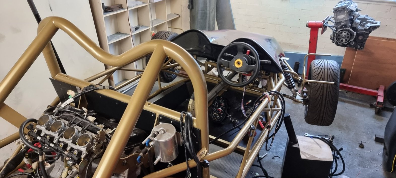
The car looks like it should work. The wings and wheel arches are in place, seats are in and most of the engine ancillaries are fitted.

Apologies for no pics from the front, the car is close to a wall, so I couldn't get everything in shot, so you'll have to make do with ass shots.

So lets talk about the dashboard. For simplicity and to get it complete quicker, I'm using the dash from the bike. This may change in the future, but lets get a few laps on the clock first. Those with eagle eyes will notice that the dash is mounted upside down. This was due to some advice from an someone who builds race cars for a living... Basically, if it was mounted the correct way up then the rev counter would be way over to the left rather than in the drivers eye line. Mounting it this way, puts it in the peripheral vision especially when hitting the higher revs.

Here's a shot of the engine 'bay'. The throttle bodies and airbox are now in place amongst other stuff. I thought that the airbox would be uglier and stick up more, but as it is, I can live with it. There are alternatives, but they're not cheap, so it's another thing on the list to consider later. There's still more to be done back here, with the main bits being the starter motor and the gear shifter.

This is as close to a front view as it gets. The seats are in, and fit (phew). The drivers seat does need to go back a bit once the fuel tank is moved to the passenger side. This view does give a good view of the rear wing which is a monster! Lets hope it's better than the Countach rear wing which actually created lift.

I can't finish this post without giving a special shout out to Len of Wildmoor Motorsport. Len agreed to help me finish off this project along with Callum who works with Len. Sadly, Len passed away earlier this month which is a true loss to motorsport. Len was a top bloke and had a wealth of knowledge and experience and will be sadly missed. RIP Len.


Friday, 27 August 2021

More oil

[I found this old unpublished post, I'm just going to hit 'publish' on it now, no idea why I didn't do it back in the day]
I ended a previous post on a cliff hanger, I'd just sheered a bolt when putting the sump back on. Not good.

I spent some time pondering what to do about this, can I bodge it? Do I need 14 bolts? If it's snapped far enough in, can I use a shorter bolt?

Do I drill it out? That sounds tough, especially lay on my back, drilling out a steel bolt from an aluminium engine lump. That could will go wrong. I consulted with my advisors; perhaps I could use the sump as a guide for drilling it out? Maybe use an extractor, then drill out a wider hole, tap it and fit a heli-coil.

I hadn't actually inspected the damage, so I attempted to remove the sump, I wasn't sure if it would come off as I didn't know where the bolt had snapped. It came off dead easy. Great. Even better news was that part of the bolt was sticking out, so I was able to get some purchase on it with some pliers. Turns out, I could get it out with my fingers, it was that easy. So basically, I made you read these last four paragraphs when I could just have said I unscrewed a bolt. Anyway, it was very relieving.

I took this to mean that the bolts were rubbish, so I got a new set of better ones and refitted the sump, and torqued them up without incident.

Sticking with the oil system, I purchased an oil cooler. As most things, this wasn't as easy as it sounded. The Hayabusa engine has some non-standard connections where the oil pipes connect, so I needed some way of getting off the shelf pipes to fit. Plus then when choosing an oil cooler there are four different standards for specifying the width of the inlets/outlets, of course the pipes that go on these use different terminology, so I can't just buy a size 8 cooler and size 8 pipes, that'd be way too easy.

After some hunting, I found that, the good guys at Extreme Engines do a conversion kit for the Hayabusa engine that converts the odd Suzuki format into one of these four standards (JIC/10). So it made sense to buy an oil cooler that was also JIC/10, then all I needed were some pipes to fit, oh and the pipe ends.

To help sort all this out, I contacted Speedflow who were very useful, and I send them my thanks! They can supply the cooler and the pipes, cut to length, and they'll fit the ends for me free of charge. 

At this point, as they were so helpful, I didn't bother shopping around as they deserved my business and ordered a 16 row, Mocal oil cooler. Again the size of the cooler was up for debate, and 16 rows might sound over the top for a 1.3l engine. However, the cooler does sit at the back of the car, so it's not going to get a lot of ram air, plus it's behind the hot engine. The only disadvantage that I could see for going for a larger one is that it may take longer for the engine to heat up, but that can be fixed if necessary.

So with the cooler delivered, I set about making the brackets, I know what you're thinking, I must be a dab hand at making brackets by now, but as always, everything is a challenge. With these brackets, the challenge was not having enough hands, and I ended up having to hold the cooler and the brackets in place and mark out the cuts using a Sharpie in my mouth.

The brackets holding the cooler in place.
I knocked up some prototype brackets in aluminium and then Steve at work created me a pair in stainless steel. I'd not worked with stainless before, and it's certainly more of a challenge than allooooominum!

So with the brackets made, I opted to paint them in the same colour as the chassis, MEV Exo cars had provided me with the RAL code of the paint colour, so I had some spray paint made up matching that and then went through the rigmarole of prime, paint and then lacquering.

Progress

Finally, some progress.
After another lengthy hiatus, work has started again, only possible as I now have help and the car is in a proper workshop.

Lots of decisions to be made, firstly I was never happy with the fuelling setup. Twin tanks complicates things and everything I read about them leads to problems. So the one behind the driver (me) can go. The tanks are 2.5 galleons each, so will be fine for a track day session. By losing the driver one, it also helps balance the weight if there is no passenger (even with a passenger, my COVID ballast will take some balancing!). 

Without that tank it also means that the driver seat can go backwards a little to give my lanky legs a little more room. However, there is also another use for that space which I'll get to later.

Next decision was around the gear changes. I wanted an electronic paddle shift, but that costs £££. From talking to the experts, they're also trouble, they need too much power and you risk losing spark and stalling which is something I'd rather avoid. An alternative is to go with hydraulics, but that costs £££££ and again is complex with either a compressor needed or having to top up a tank.

So the decision is to go with a stick shift, mechanical. It's not ideal, and will cost lap time, but not as much time as breaking down. Plus it will still be fun and I can always change when I save enough pennies.

The big progress has been the wiring, the loom is now extended and mostly in place. A lithium battery is on order, none of this old school acid or gel malarkey! This does beg the question of where to put the power commander, rectifier and all that gubbins. I wanted it under the nose cone on the passenger side, but that meant lengthening a load more cables, so it can go in the handy position which has just been made available behind the driver where the 2nd tank was going to be.

One more expenditure, a water pump. The pump on the 'busa lump isn't enough to circulate the now bigger system with the upgraded radiator that I fitted, so an additional pump is on it's way.

In the final picture here, you can also just make out the clutch slave is mounted on a custom bracket. Not sure how it's meant to go according to the kit, but as I never got a manual...

Monday, 28 January 2019

Brakes

It’s fair to say that it’s been a while since I last worked on the car, over a year in fact! The problem has been that I keep getting stuck, find out I’m missing parts or just haven’t had time. Since then though, I’ve brown the engine in my track bike, crashed my KTM (and fixed it), and had a baby.

Who needs instructions with skills like these
I figured the brake system couldn’t be that difficult but despite having a sealed pack labelled “Mevabusa brake kit”, it didn’t actually contain everything I needed. I was missing a T-piece, some banjo bolts and the cables that connected the master cylinders to the reservoir. All of this should have been in the "kit in the box", but then I was also promised instructions, and they never materialised either.

The supplied reservoir
Speaking of the reservoir, it was a second hand pot with duel outlets with scanky ripped hoses attached. I opted to buy 2 new reservoirs, this way I’d know the exact sizes of the outlets for the hoses I needed to buy and I could have separate systems for the front and rear brakes giving some kind of hope in the event of a failure (it’s me building this thing remember!). Also if I need to work on it, I only need to bleed 2 corners at a time.
Look at the pair on that...


Plumbed
When I had all of the right parts, plumbing it all together was pretty easy, and everything is now tightened up. I’m not putting fluid in yet as the car is still up in the air on blocks so it’s not exactly going anywhere plus it’s highly likely I’ll need to disconnect things as I do more work around each corner. It is very tempting to whack the fluid in though, it would mean something on the car actually worked!

Sunday, 6 November 2016

Parking brake

Brakes are an essential park of any vehicle (apart from unicycles) so I thought it time to fix up the parking brake.

I'd already run the cables, and physically mounted the brake, so it was just a case of putting it all together and adjusting it, should take 10 mins.

Several weeks later, I've now mostly finished it. I'm sure there's an easy way of getting the cables tight, but I didn't find it. 

I very much dislike these cables.
The handbrake has a short cable coming from it which goes into a joiner which in turn attaches to the cables from the brakes. The joiner doesn't attach to anything and just floats. This is fine, but getting the cables tight and then holding everything in place took a few attempts. 

While playing with the handbrake, I realised that I hadn't bolted it down with big enough bolts, so I decided to use M10s and took everything apart.

Now, I'd used rivnuts, so I had to drill those out, but when you do that, they just spin so I ended up hack-sawing them whilst trying to hold on to them so that they didn't drop into the chassis and spend the rest of eternity rattling around annoying me. This took a while but finally they were out and the handbrake was now bolted in a lot more firmly with the M10s.

I connected the cables back up, and this is when I discovered the adjuster on the handbrake itself. I wound this all the way down, did everything again and then adjusted back up and as far as handbrakes go, it works. You pull it up and it applies the brakes, sweet. It's just not quite good enough and all needs tightening up a bit more. I did pin the cables down in the end with some p-clips which isn't shown in the above pic. This was a pain as there was no room to work and the p-clips kept wanting to spring around the garage. Lots of deep breaths were taken during this process.

All cuts made
The next stage was getting the tunnel to fit over the handbrake. This also meant cutting slots out for the chassis cross bars as I wanted the tunnel flush with the floor. Some people built the tunnel up which means you don't need to cut it but I didn't like that so much.

The slots were measured about 15 times before I cut them, and by gods were kind to me as everything lined up nicely. I could test fit the tunnel, albeit without the slot cut out of the top for the handbrake itself. So far, so good.

The final part of the puzzle was cutting the top hole, so I put this off for a bit, then one lazy cold Sunday, decided that I'd brave the weather and sort it out.

Armed with some masking tape and a red sharpie, I marked it up, and it was a little easier than expected, in fact, I'd measured too well and hadn't quite given myself enough slack, so recut the hole a little bigger.

The end result is a working handbrake and a tunnel that fits! I do have a leather shroud thing for the handbrake to make it look nicer, but there's no point putting that on yet. Now I can put the second fuel tank back in again and move on.


Practially on the road...

Sunday, 11 September 2016

Progress

Progress has been made in various areas these last few weeks...
There are about a million steps missing still, good
job you can zoom out a lot!
Firstly the organisation of the build has changed, in that as well as my spreadsheet, I'm using RealTimeBoards to whiteboard things out which is a good graphical way of seeing what needs to be done next (I'm in no way affiliated with those guys, I just think it's a great tool!)

As well as planning, I've got some help now in the form of Martin, who will try and figure out WTF I'm meant to be doing.

In terms of actual progress on the car, well focus has been on the rear corners. You see, I want to get the braking system done next, but before I could do that really, I knew I had to finalise the rear corners as they'd have to be dismantled in order to get the rear cycle wing stays in place.

The front wing stays (the bits that hold the cycle wings in place), were easy, in that both stays were jointed together to form a single piece of metal and the holes where they connect to the front upright were pre-

drilled and set. The rear stays however were in two parts and there were no holes.

This meant that they could go at any angle and distance which gives a high probability of me stuffing it up. The rear uprights are also made of mild steel and quite thick, so I wasn't looking forward to drilling them.

So we put our minds to it, and sketched it all out to scale on some A0 diagram (it was actually the back of the wiring diagram, but I won't be needing that for some time!). We came up with a plan that looked like it would work, so we reassembled the corner to test and it looked about right.

Rusty disks
The next step was doing the drilling, so I once more made use of the facilities at work and Steve made the holes.

The assembly was then fairly simple and everything is back on the car. The only two worries I have is that I'm not sure what to torque the axle bolt up to and the brake calipers pinch the disks a little...

Progress was also made in that I had a massive amount of play in the steering rack, so I took my wheel and quick release boss off... no wait, I didn't do that, because one of the bleeding bolts had rounded. Instead I spent an hour hack sawing away at it before removing it.

Once in pieces, it was obvious what was wrong, the bolt inside wasn't done up properly and when that was sorted all of the play disappeared. So that was put back together after and all was good.

Now with the rear corners sorted, it was time to run the parking brake cables (I'd call it a handbrake, but I'm trying to use the same lingo as in the IVA manual!).
The basic run for the parking brake cable

It seems most people use little clips or struts on the brake & parking brake cables to keep them off the frame, I'm not sure why, so I just cable tied mine to the chassis for now. I haven't connected them to the actual handbrake yet, because that looks like it's going to be fun job*, so I'll save that until next time.


* Read: no fun at all


Tuesday, 26 April 2016

Exhaust Wrapping

I've mentioned several times that I wished that I'd heat treated the exhaust manifold before I fitted it because (a) it's very close to lots of other stuff like fuel and brake lines, and (b) it's a bitch to get on and off.

Well, because of the work I did on the sump, I had to get it off anyway, so I figured while it was off I'd sort it out and get it insulated.

After some research, there were a couple of ways to proceed. I could wrap it in heat absorbent fibre cloth or I could get it ceramic sprayed. 

The ceramic spray is a better solution, the cloth can have gaps which means you could get a build up of heat in a spot and that could damage the exhaust. The ceramic spray also looks much better. However, the spray, if done professionally, costs £lots.

There was a hybrid solution available too. Wrap it, and then get some cheapo spray and spray it as well. Sounds like a plan to me, so after some all too familiar eBay/PayPal action, I soon had the necessary bits required.

Wrapping was fairly easy, I used two rolls in total. I'd watched some videos on how to do this, and everyone started at the top and worked their way down as you'd expect. Now, I'm not stupid, I didn't start in the middle, but it seemed more sensible to me to start at the bottom and work my way up. This way, the overlaps were layered the correct way, so if I was caught in the rain, the water wouldn't collect. Time will tell!
High Tech Spray Booth

After wrapping, I applied the spray using my custom made spray booth (cardboard box) and applied a few coats. It looked nice and I'm debating spraying the other bits of the exhaust, but that decision can be made later.

All too easy right? Well now it was time for the bit which I pondered a while over, you see, with both the wrap and the spray, you have to cure it. And that means heating it to 400C somewhere. So even if it would fit in my oven, that ain't gonna cut it.
I could cure it on the engine, run it at idle for 20mins or so is what some people suggest, but as the engine isn't running yet, that isn't an option.

Luckily there's a workshop at work, and Andy showed me the facilities. They do have a large oven, but even that won't accommodate the manifold, so was going to opt for plan B and use the hand held gas torch that's good for 800C!

Miraculously the building didn't burn down.
I took the exhaust in to work to  find that they'd built an electric kiln for a project. Some research team wants to simulate ageing of rocks or something so they'd made this booth which my exhaust would fit in.

We fired this up, it was untested, so they had no idea what temperatures it would reach. The extractors were switched on and the room started getting warm and after about a minute it was up to 130C. At this point I left because I didn't want to be in the workshop when the fire alarms went off as that could take some explaining.

Later in the morning Andy from the workshop came to see me and said that it was all done, the home made kiln had reached 480C which was well above the 400C that I needed. Sweet.

I went back down to the workshop to take a look, and we couldn't resist getting the torch on it just in case we'd missed some bits :)


Monday, 4 April 2016

Sump

I'm alive! It seems like a long time since I've done any work on my car, in fact, I'm pretty sure that the Spiderman movies have been rebooted 3 times since I last tightened a bolt, but now I'm back.

I do have a bunch of half written articles, so although it's been forever since a post, it's only been eons since I worked on the car.

Anyway, today I fitted a new sump. I didn't need to do this, but it's advisable, and it still may not be enough, you see, as the engine is designed to be in a bike, when a bike corners, it leans, centrifugal forces and gravity kick in and everything is good. However, when the engine is in a car, the car doesn't get the same sort of lean angles through a corner (unless you're doing something very wrong) so the oil surges and things blow up. I don't want my engine to blow up. 

On a normal trip to the shops, it'd probably be fine, on a track, maybe not so much, and this is where I may not have gone far enough, as the ultimate mod would be to have a dry sump, but they cost a lot and it's probably complicated.

So I decided to buy a kit to sort all this out, and after some research the Extreme Engines Low Line Wet Sump with Baffle Plate was the one I opted for.
I explained to the guys at Extreme Engines my level of competency and they assured me that it was easy and that instructions were included. Great.

The kit comes with a clutch baffle kit too, so I decided to start there. Step one of the instructions read Remove clutch assy. Now for a start, I'm pretty sure using the entire word assembly could have been used, but I cracked the code.

After removing the clutch housing, I was staring at something that reminded me of the Giant Hadron Collidor:
The Giant Hadron Collider on the left, my clutch on the right.
Now, just six simple bolts to undo to get the clutch assy removed, simples. Hmm, it turns out that those six screws hold each clutch plates in place, and those things look quite fiddly and need to be in exactly the right order and rotation. It was at this point I thought I'd put the six bolts back in and do the sump instead, surely the clutch baffle isn't that important anyway.

Oh but those six bolts are sprung, and add in the fact that the chassis hampers my leverage, what a bitch they are to put back in. I'd read that it's a good idea to swap out clutch springs for heavy duty ones. The logic being that when fitted on a bike, the clutch is hand opperated, but on the car it's your foot so a bit more resistance is nice. I did this and despite having lots of spinach, when writing this up the day afterwards, my hand still aches now.

So the clutch baffle was thwarted at the first bullet point of remove clutch assy, so I wasn't too optimistic about the sump side of things.

This is where my lack of enthusiasm crept in, and had a slight hiatus on the project that I mentioned at the top of this post. So today, I cracked on, and removed the sump. I was worried that the bolts holding the sump on would shear, there are 14 of them and it would only have taken one to be a bugger, but no, they were ok in the end.

The rubber mallet was needed to get the sump off even with the bolts out as the grime on the engine was holding it together. I managed to avoid getting covered in oil, I know that was what you were all waiting for, but no, I'd thought about that. 
Yes, that is a rip, and a footprint.

Proper engine stuff now. There was one slight problem in that the instructions had been left out in my garage during my hiatus, and they had faded so much that I'd seen better looking treasure maps.

The arrows on the drawings were very very faint, and any text in red had faded completely. But surely nothing important would be written in red so I was probably ok.

"Remove three main bearing bolts". Which are the beari...oh got it. Those boys were in pretty tight. 

I was a little concerned as I'd read ahead a little and it mentioned to make sure the o-ring was in a certain position. I didn't have an o-ring, and o-rings sound important, I should probably have one, why wouldn't I have one? Maybe things will make sense if I carry on.

Removing the rest of the bits was fairly simple and came off easily. Everything was out now and it was time to fit the new parts. The kit contained smaller bits of what I'd taken out so that they'd fit in the new shallower sump. No problem. 

Still no o-ring, so I double checked all of the packaging and then noticed that there was one still sat neatly in the neck of the oil pickup that I'd removed. Phew. 

Putting the new parts in was pain free, although tightening to the adequate torque felt like I was going to do some serious damage.

I threw caution to the wind and fitted a new gasket, and hey presto, job done.


Before & after
Spoke too soon. A bad thing happened.
Ooops.
Whilst tightening up the bolts that hold the sump in place, I set the torque wrench to the specified 7ftlbs and on the first bolt; tighten, tighten, tighten, snap.

That's right, the first bolt sheered which is annoying as the wrench certainly hadn't pinged to say that it was up to torque and it was set right. I can only guess that the various adapters that I had on it to fit the 8mm socket had thrown the calibration.

Not quite sure how to fix that, just when I was getting somewhere...


Tuesday, 26 May 2015

Water works

A minor update today, but as a milestone has been met, I figured it was worth posting about; finally the water cooling system is complete.

I posted earlier about switching to a bespoke radiator and that meant reworking the pipework at the front and making some custom brackets. The facilities at work came in handy again for the brackets as they have a proper machine to apply the 90 degree bend that I needed rather than me just twatting it with a hammer until it fit. So many thanks to Steve for sorting that.

The pipework was fairly easy too, luckily I had enough spare bits now to do the necessary joins.

At the rear, the pipework does get awfully close to the exhaust manifold, looking at some pics I notice that others have wrapped theirs, but there's no way I'm getting that bastard off again to do that, so I'll see how it goes and maybe fashion some sort of heat shield in the future. 

I did have to move the rear pipework to make way for the fuel system, but it was only changing the angles a little so that worked out ok.

So there we have it, another milestone complete. I'd have finished the fuel system too if the place I ordered the clips from had sent the right amount, god bless eBay.

I now look forward to 4 years in the future when I can finally fire up the engine and put some heat cycles through it all and play spot the leak.


Wednesday, 8 April 2015

The final engine mount...

Today I'd like to talk about one of the engine mounts, which turned out to be a lot more of a struggle than it should have been. The mount in question is the one highlighted in red in the picture below. You'll notice that it's one of the larger mounts and one of the first to go in...


I know, it needs a clean...
As you may recall, getting the engine in was a bit tight, and the bolt was put in place then, but as it involved a lot of brute force and grunting at the time I just wanted them in place and I'd fit the necessary spacers afterwards. Mistake number 1.

You see once the engine had settled everything got even tighter, so when I pulled the bolt out into the position in the pic above, the engine moved just a millimeter or two. I'd taken it out to put the correct spacer in as that plastic one in the pic is clearly not the right size. This is where mistake 2 comes in. You see, due to the length of the bolt, it fouls on the chassis meaning you can't actually get it out without moving the engine which I'm never going to do again. So that meant, if I couldn't take the bolt out, I couldn't fit the spacer.

Oh well, I'll just pop it back in again and add it to the list of worrying things to fix later. No, wait, the engine moved didn't it, that means that the bolt won't go back through. Plus, because the chassis is there, no matter how mad you get, you can't hit it properly with a hammer.

So I got my Dremel out, only my Dremel isn't like the nice mains powered one I borrowed from work, mine is a wiener little crappy battery powered one that cost me about £8 from eBay. 

Sometime later, I'd shaved the paint off the chassis and just about made enough room for the mount to slip back through. I then cut some spare rubber hose, slotted it around the part where the spacer should go and tightened it all into place. It's not perfect, but the hose is squeezed so tight it'll absorb any movement, I'm sure it'll be fine.

At last, all engine mounts in place.
Not the most exciting story I know, but these are my daily struggles, one bolt can take an hour!

In my last post I mentioned that the throttle cable that I have is way to short, well after reading some useful build logs on the Tr1ke forum, I urm have to admit that the cables I have aren't exactly throttle cables. In unrelated news though, I now know how the handbrake cables attach. Now to order a throttle cable...

If anyone is reading this who isn't on the MEV forums, then I'm currently hunting for a helping hand. I'm based in Birmingham and am quickly running out of things that I can actually do myself. So if you fancy giving a hand, either just advice or mucking in, then drop me an email at mark.connop@gmail.com.

Tuesday, 7 April 2015

April 2015 Update

It's been some time since I last posted, but don't worry, you haven't missed much, I'm still some way away from sticking it in a gravel trap just yet...

Progress has been slow, very slow, way way too slow. The problem is that I have no clue how to do stuff, so it's been a lot of pottering around doing not a lot and then a break of a month and so on.

So what have I done? Well, the cooling system is mostly complete, I changed my stance on this pretty close to completion. I was originally going to use the bike's radiator and then realised I'd need a header tank to actually fill up the water as the rad sits quite low compared to the engine. I ordered a custom header tank and went with a slightly higher than standard pressure cap (I should refer to some science at this point as to why I did that, but really it was down to Googling and a shrug of the shoulders). This meant that the pipework involved now no longer matched how it was on the bike. I needed a diagram.
Plan A: Using the 'Busa's radiator


After checking this out with the forum lurkers, I carried on with this plan, and pretty much had it all complete, however after reading other people's experience and noticing that every car that RTR had at their place didn't use the 'Busa rad, I decided to swap the radiator out for something a little more upmarket.

I chose the Radtec alloy radiator and after a quick call to their HQ some money changed hands. At the time of writing, I don't have it yet, so that's still to be done, but the rest of the cooling system is all in place. Time for a new diagram:

Plan B: Now with less lines!
Some incomplete pipework, I've been just as lazy at taking pics
as I have been writing this blog.
There are extra bonuses to this plan, I no longer need the small pipe running the length of the car, so that frees up some tunnel space and saves me a bit of weight, plus it makes the system a little simpler to understand. No doubt I'll have fun making the brackets to get the radiator to fit, but how hard can that be, right?!

Other than the cooling system, last year I decided that I was never going to fit in the nice lightweight moulded seats that comes with the kit. Now I quite like being shoehorned into a car, but those seats were just not going to work unless I spent 40 hours a week watching exercise videos starring the cast of TOWIE and then having a double hip replacement. Instead I went to see the good people at GSM Performance near Nottingham and spent a bit of time in their showroom with the staff there. I have to say, they were very helpful, and I decided on the Cobra Monaco Pro seats that a few people have in their Tr1kes.

The front wheels are on to weigh down the front end.
At some point I'm going to have to think of a way to get the
car off the stands.
These have now arrived, I fit in them, they fit in the car, I just don't quite know how to fit them. Ideally I'd put them on the chassis, but if I do that I'd have to go without fuel tanks. If I move them forward, then I'd have to mount them on the floor, and I'm pretty sure the floor wouldn't like that. So I'm probably going to have to make some extensions to the seat bracket so that they can fit to the chassis. Just don't tell the FIA.

Now I know roughly where the seat is going, I found a place for the handbrake, that's now in place, although not cabled in because, you guessed it, no clue how that stuff works.

Fuel next. That's got to be easy, a couple of tanks and a pipe to the pump, right? Getting the tanks in wasn't too bad actually, although some of the holes I needed to drill were impossible to get my drill into, so I borrowed this rather handy right handed drill (it works in your left hand too).
More tanks than a Brad Pitt film

After a few more holes to allow pipes through, the tanks were physically in place. And this is where I'm at with the fuel as I've no idea how to pipe them all together. The schematic for the fuel system on the 'busa isn't much use as it doesn't have twin tanks, and I need breathers, and swirl pots? More research needed.

Some little things; I decided that I should put the throttle body back on the engine and then I could fit the air box. The throttle body was a little tricky at first but overall, it was ok once I'd loosened off all the fasteners. The air box could then go on, but there was no point until I'd cabled up the throttle cable, so I just tried it on, then put it back where it had been sitting for the last 18 months.

So the throttle cable, how does that work then? I received two cables in the kit, I assume one is the throttle, the other the clutch? But neither are even half the length I need? I can't see anywhere to attach the cable to the pedal or retain it even if I drilled a hole myself. Looking at some photos, I still don't have a clear idea, but could have a go at attaching it to the pedal, but what's the point as it isn't long enough, should I be attaching it to the Busa's cable to make one super cable? Plus I seem to remember there being several (3?) cables on the bike. Two for the throttle, one for the choke? Not sure there, best leave that.

I'm sure there are lots of other things, such as the removable steering wheel boss, brake calipers and so on, but that'll do for today's update. I'm hoping to have another play tomorrow (especially if that rad turns up), maybe start hacking away at the nose cone. 


Monday, 2 June 2014

Engine In

Bit of a milestone this one, but the engine is finally in. It's been mostly in for a since December, so just under six months later and job done.

Not to get too excited of course, it's just in place, it's not running yet, lots to be done before that can happen.

So why so long?

Well... there are six engine mounts, two at the bottom which go all the way through the engine block, and four at the top that just bolt into the chassis, two each side of the engine.

Back in December, Paul and I wrestled the bottom two mounts into place just to get it roughly there. This was the easiest way as it would allow us to pivot the engine then to line the others up. The two bottom mounts were VERY tight and it took a lot of careful manoeuvring (aka hitting shit with hammers) for them to fit. 

We then lined up the other four mounts with the holes and found that they didn't exactly line up, I could partly get one of the bolts in...
Can't. Quite. Fit. If only.Could. Just...

And that's where it stayed until today.

I'd decided that making the holes bigger was going to be a pain, so I'd been doing other things, but really, I need it sorting, so after various thoughts on how to do it I had a 2 min chat with Mike at work. A few mins later Mike appeared with his Dremel.

So I set about expanding the holes and boy did sparks fly. Now I don't own any safety goggles so I wore my MX helmet as that has some goggles with it (I could have just taken the googles off, but they they'd have needed adjusting to fit without the helmet, that all sounded like effort so I just wore the damn helmet).

A few minutes hours later and all four mounts were in. The spacers that were provided with the kit don't quite fit, so I'll need to mod them, and because of that the Hayabusa engine mounts aren't quite the best length, so I'll need some washers and some different length mounts, but all in all, a good job done. 

Not sure now why I put it off 6 months! Which reminds me, I know a good joke about procrastinating, but I'll tell you that later...

Monday, 7 April 2014

DIFFicult

A long, long time ago in a garage far far away, I started building my car. Well, after a very slow going winter I finally have some progress. If you thought I was going to say that it was finished, have you learned nothing from my previous posts?

Tonight I did some work on the diff, the clue was in the title, I did a play on words thing and changed 'diff' into 'difficult'! You've missed these posts haven't you... I'll get my coat.

Where did I leave off? Oh, I haven't even talked about the engine have I yet... well that was fun.

The car looked very pitiful when thrown on the floor.
Tim and I had great fun getting the engine in place, you see the engine has to come in from under the car, so I took the opportunity to turn the car 180 degrees (not that way! I mean so that it was facing the other way!).

The engine was then hoisted in which was interesting trying to keep it level. We got a couple of mounts in place and called it a night as we hit a slight snag.

Check and check again. Did it your side slip? No, did your
side? No. Up a bit more? Urm... let me check again first.
You may remember that one of the engine mounts was screwed and needed re-tapping. This was a fairly simple affair with thanks to Steve for lending me the taps and Paul for showing me what to do during an hours *ahem* lunch break.

It looks tiny. Hopefully it'll be underestminated ;)
So with the mount sorted, Paul and I decided to get the engine in place. Tip of the day: If you're reading this before you've done it, do the two bottom/rear mounts first, you can then pivot the engine much easier to get it at the right angle for the top/front four.

Millimetres make a big difference in this game. Typical,
the mount that is furthest out is the one I had to re-tap.
Oh if only it were that easy, you see the chassis doesn't exactly line up with the engine mounts. It was a real pig getting the bottom two in as things were so tight, but with the force of some Icelandic strong men, we made it work. The top four don't exactly line up though and I'm going to have to get creative with the holes in the chassis to make it fit.

Never-the-less, with the engine in place, I could crack on. I did some other bits which I'll make separate posts about and fast forward to tonight's work, and the title of tonight's post; the diff.

The diff comes in three parts, two mounts and the diff itself. It's a fairly heavy piece of kit, holdable in one hand but really two's needed to lift it. When all three bits are together it looks a bit like a Tie Fighter.

I originally put the mounts in place and then tried to slide the diff in, but the gap was too tight as part of the diff inserts into the mounts. Fair enough, so I assembled the three parts and then tried to slide it in, but it didn't fit, the gap was still too narrow. Hmm.

So I got out the ol' measuring stick (aka a ruler), and found that the diff with the mounts was 17.7cm wide (that's 177mm for you engineers). The gap however was only 17.0cm, so if my maths can be trusted, the gap is 7mm shy of what it needs to be. Just for completion's sake I measured the gap at the bottom, this was bang on 17.7mm, so it looks like the top is definitely out. As it's part of the chassis this was already assembled by Road Track Race so it wasn't anything I could have done wrong. I was going to drop them an email (they've proven very helpful and responsive in the after sales department, so don't let me lead you into thinking that they're a bunch of cowboys who just sit in the factory counting my money).

Anyway, before emailing them I sat and had a little think and decided I'd try and push the diff in from the bottom rather than slide it in from the top. I knew the bottom was wide enough, so maybe once it was mostly in, I could flex the 5mm aluminium mounts or something.

It probably would have been a long easier with a second pair of hands, but it was still light outside so I wasn't giving up, besides, yesterday's F1 race kicked ass so I was dreaming of getting the damn thing on the track.

It went half way in ok with some jiggery-pokery and the three parts were assembled at this half way stage. After that I tried getting into the gap at the top and it wasn't playing ball, 7mm was too much to flex.
So, so tight. (Stop sniggering)
The chassis is powder coated though which is a couple of mil, so I sanded that back, which still left about 5mm to make up.

Luckily I own a hammer. So doing my best Jeremy Clarkson impression I did some light taps and just about got both sides inside the gap. From there, I could gently tap it further into place until it actually fit. Hurrah!

With a certain sense of accomplishment, I unboxed the drive shafts and temporarily slid those in and everything seems to turn like it's meant to turn and is decidedly more car like now.

Excuse the wonkyness of this picture, I was stood on a chair
with the camera above my head. Believe it or not, this was the
best of three photos.