Sunday, 10 November 2013

Bulk head and engine movement

It's been a while, even though, don't expect a picture of the car on the road just yet!

Progress has been split between three different stages; stripping the 'busa, engine work and assembling the car.
One wheel on my wagon

I'll start with the 'busa strip. It's probably as stripped right now as it's going to get. With the engine out, I salvaged a few other parts that I needed like the dash, rectifier and the brake/clutch pots.

No dramas here really, the excellent Suzuki manual tells you everything you need to know with good diagrams and lots of arrows. I still don't have a manual for the Mevabusa that I'm building, but hopefully it'll be of the same ilk when it shows up.

The rear subframe and wheel are off now and the bike is as light as a feather. I don't have a socket to fit the front axle yet, but it's practically at the stage where I can just throw the remainder into a corner now and dust off my eBay account.


Not quite a one man job it turns out
On to the engine work, if you remember one of the exhaust bolts sheered off when I was taking apart, so I opted to take it to work so that Steve could work his magic and voodoo it out. I'd been lent an engine hoist so when Tim and Tommo came over to plan next year's bike trip I got them to lend a hand and hooked the engine up (also cheers to the Moss man for lending me his hoist gear).

Once it was hoisted up I could winch it into the boot (americans: This means trunk) of my Focus, although in reality I couldn't get the hoist close enough, so I gathered some troops and came home one lunch hour to man handle it in. Paul and Sam were the unlucky helpers but it was fairly easy, the engine isn't that heavy, so even when it came to getting it out the other end it was fairly easy.
The replacement stud is just under the rightmost port.

I left it in Steve's capable hands who drilled the bolt out and replaced it with a stud that was glued into place with some atomic glue or something! Sam and Paul once again gave me a hand getting the engine back to base and I gave it a clean once the rain held out. From the engine side, it's now ready to go in I think...

Which brings me onto the car assembly. There's been some discussion and work on the corners getting the bearings and brakes sorted, but I'll put that in a separate post once they're done.

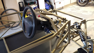
So in preparation for the engine going in, I've put the rear bulkhead in place. Although mostly cut to size by RTR it did need some remaining cuts to get it around the diagonal engine braces on the chassis. They're also sided so I had to be very careful with the measurements. After the cutting I tried it for size and found I'd been too accurate (check me out), where the diagonals meet the main chassis there are blobs of weld so I had to adjust my slots to take those into account.

I wanted to fit the bulkhead with rivnuts now that they're my favourite thing, plus I wanted to get good return on investment on my rivnut gun. It also has the side effect of making it removable which I'm pretty sure I'm going to need for some reason that I don't know about yet.


Those holes in the floor are meant to be there!
Three quarters of the chassis that the bulkhead connects to is curved which makes life difficult so extra care was taken to hit the centre of the curve (I completely missed on one side, but made it work). With that done, I vinyled up the cabin side of the bulkhead and put it in place only to realise that I'd applied the vinyl to the wrong side. Doh.
The chair in shot isn't part of the final build, I opted
for bucket seats instead.

Not a problem, the nice people where I'd got the vinyl from had given me way more than I'd asked for, so it means that both sides of the bulkhead are carbonified.

I'm quite pleased with the results. It took a lot longer than I imagined, but then everything seems to! I'm also two bolts short of being able to attach it properly, so I'll pick a couple of those up tomorrow to finish it off.


Sunday, 20 October 2013

Engine out

Today a major milestone was achieved, with the help of Tim, the engine is out of the bike!

The bike in the background is actually
quicker than the Hayabusa right now
This weekend was mainly spent doing that, with the last few bolts being a bit of a pain. Luckily I'd read ahead in the workshop manual and saw that a special Suzuki tool was needed to get some of the engine mounts out. Looking online and these go for about £90 which seemed a bit steep to me, so I looked on a few forums and a bunch of people make their own out of a long socket and an Dremel (note, it pains me to call it a Dremel, that's like calling a vacuum cleaner a Hoover, but still, everyone knows what I mean if I say Dremel). However, I don't have a Moto-Tool Dremel and it looked difficult, so eBay helped me buy a Chinese knock off version of the Suzuki tool for a fraction of the price, God bless the Chinese and their lack of acknowledgement of international copyright.

"I'm gonna make you great again"
To be fair, the tool worked well and all but one of the engine mounts came off quite easily, there was one however which took some leverage and I was pooing myself a bit that it was going to snap off as I was using a 2 foot scaffold to help turn it. It was all good though, it came out eventually so then it was a case of lowering the engine out and popping it on the side for a clean, oh and that damn exhaust manifold bolt needs extracting.

Steve at work lent me his engine hoist, so Tim and I set that up. Tim thought that we'd better test it first so he hoisted me up using it. It's good to try these things :) However, we're missing the chain to connect the hoist to the engine, so there's no trying it for size just yet.


My new cafe racer


Wednesday, 16 October 2013

More Busa Work

I've spent the last couple of weeks continuing to strip the bike engine.

I managed to get hold of a good workshop manual that has a step-by-step guide on removing the engine which I'm following religiously. On top of that, I'm labeling everything, although I'm labeling it with what I think it is, so as long as I still think it's that when I'm connecting it back up again, I'll be ok.

Obviously there have been a few incidents along the way, luckily there have been no more smashing lights however. In getting the fuel tank off, I had to clamp some pipes to stop the fuel spilling. It turns out that cable ties aren't adequate for clamping pipes so there was a minor fuel spillage on my garage floor. Never mind, it probably needed a wash anyway.

Next, the radiators had to go, yes, I spilt the coolant too. My garage floor is now spotless. But off came the rad and a bunch of other bits too.

I drained the oil, I'm learning, I didn't spill that, in fact I left it draining for a few hours while I carried on and then put the oil screw back in finger tight and locked up one night. Next morning there was oil all over the floor, apparently finger tight isn't good enough and there was still some oil in the system. Now you thought my floor was clean before? It could now double as a set in a Mr. Muscle advert.
Proper engine bits here!

Anyway, back to pulling bits off the bike. It's quite an enjoyable task, and it really makes you appreciate the work that goes into designing the things. It's a 14 year old design but it's also still a 200mph bike and there are sensors just about everywhere. I take my hat off to Suzuki. 


Ooops
Along the way there was one mishap with one of the manifold bolts, it kind of broke which is going to be a real pain to get out, I'll wait until the engine is out I think as it's at an awkward angle to work at.

The workshop manual has 12 pages on how to remove the engine, although some of the bullet points refer you to another section which is another 4 pages long. However, I've broken the back of it now, and I think I'm probably only about an hour away of getting the lump out.

So why stop I hear you ask?
Well, because of torque. You see, although I now boast a moderate toolkit, I don't have any BIG tools, like 32mm and 36mm sockets needed for the front sprocket and rear axle. I tried and tried and still couldn't blow the house down (sorry, wrong story) couldn't get them to budge, so I called in Tim to assist. The front sprocket is a 2 man job anyway as someone needs to stand on the rear brake which you apply brute force, but with my wiener socket wrench, we couldn't get it to move. It was the same story with the rear axle.

Luckily Paul at work has some decent wrenches and a nut cracker, and Mike has a 36mm socket which I borrowed. With these, the rear axle nut (72ft/lb) came off quite easily, but I haven't managed to get the front sprocket nut off yet (105fl/lb), but then I have been trying to press the brake myself while also using the wrench (all those years of Twister haven't paid off). So I'll call in help again probably this weekend.

So although there has been progress, it's been pretty slow, but it has been educational.

Here's a picture from a few nights ago, further bits have come off since this was taken but only little bits.


And to think I never liked naked bikes

Ninja edit: The front sprocket nut is now off too, hurrah!

Wednesday, 2 October 2013

Stripping

I needed to strip, in fact I spent most of the night stripping. Haha, I'm so funny, I meant stripping the bike, oh how we all laughed.


Before I got to work on it.
I needed several parts from the Hayabusa, things like the dashboard, radiator, wiring loom, mirrors, switching gear, oh and that little bit called the engine.

The rest of the bits have a date on eBay, but that's a little way off yet.

I'd delayed pulling the bike apart as I was having fun using it for my daily commute, with my KTM still being repaired from it's incident with a Land Rover  (stupid woman!), I'd only had my DRZ-400 all summer. So it was quite nice to have something with a bit more umph. Now I only live 3-4 miles from work, but it's odd how occasionally it would take me 15 miles to get home :)


A pile of plastic
Anyway, the time had come, I had to start work on it, and it was coming to the end of the month, so I needed to get it SORNed before I lost another month's tax.

The fairings came off quite easily, taking bikes apart is much easier when you don't have to remember or think about how to put them back together again afterwards. So after a couple of hours, I had a pile of plastic. The nose was a little trickier, but it soon relinquished, and it was just after taking this off when I thought that the bike was still in fully running order...

I wasn't about to blast off with a new naked version of a 'busa, but I did need to take some pics and videos. So that I knew what the startup sequence looked like, I filmed that to compare with when I had rewired it all for the car.

I then had the bright idea of firing up the engine, to record the sound of the cans so that when I sold them, I could demonstrate how good they sounded.
This is what happened:


Yes, after blipping the throttle, the bike was such a monster that the ceiling lights fell down and smashed. I think that's enough stripping for tonight!

Here's where I'm up to:


Monday, 30 September 2013

Catchup...

It's been a while since I've provided an update for a few reasons, firstly my inane ability to procrastinate, but also because progress has been a little slow. Allow me to explain and bring you up to date on the various bits and pieces.

Steering Rack
Home made tool
The steering rack as you may remember needed disassembling so that a new rack and pinion could replace the standard Sierra bits. The new parts make it a quick rack, so basically less turns from lock to lock which will make the car a little more nimble on track.

The problem was that Ford decided to make just about everything that needed to be removed to require a custom tool. Obviously I didn't have a custom tool, so Steve at work used his wily brain and sorted things out. Fast forward a few days and I just needed to get the bearing off the old pinion and remove the spring system to allow to rack to come apart.

The bearing was on tight, tighter than a camel's bum in a sandstorm in fact. Luckily I had access to a big vice and an even bigger hammer. Bosh. Sorted.
Brand new but rusty,
going in the bin anyway

The spring system required some welding to make a tool to do the job. Of course, I'm not allowed anywhere near something like that, so Steve sorted it out while I hummed the A-Team soundtrack in the background. Once we had the tool it was easy work.

The rack was swapped out for the quick rack, but it was worth noting that even though the original rack was brand new, it still had signs of rust on it despite it never been used and covered in grease, it just shows what the shelf life does!

This is where the plastic nut needed to go. That's filings in
hole from work done to get it back in (don't worry, it was
cleaned out before put back together.
Putting it all back together wasn't simple either, the nut holding the spring system in was plastic and was easy to damage, mainly because Ford had 'knocked' in the metal around it so that it wouldn't slip. So a little bit of filing and lathe work and it was back in. It was prouder than before which was a worry to begin with but as the pinion it was pressing against was wider, that made sense.

The pinion cover that was tough to get off was tough to get back on too, Steve again sorted this as I don't think he fancied me throwing his tools through the window!

With that sorted I could do the rest at home. Now that probably doesn't read to hard, but as I did it at work, it was hard to get the time, and Steve's a busy man too, so it took a few weeks bit by bit, and my thanks do go out to Steve I'd probably have given up and kept the original rack!

Steering Column

The universal joint that connects
the column to the rack.
Ah, the column. I was dreading this as I read the instructions for it some time ago. It basically involved stripping the existing column, sawing a bit off, welding some bits together, then judging if it was right, then welding it again. I showed it Tim as he made this sort of 'hmm' noise, so we decided to put it to one side and come back to it later. Well it was now later.

Now, remember that the instructions that I'm following are for the Tr1ke, not my actual car, but this bit was all the same in theory as the front end was the same. That may be so, but Road Track Race (RTR) have made things easy since then by doing the cutting and welding already. I didn't realise this though for some time, so much so that I'd told the good folks there that I was missing a part but when Harry from RTR dropped in one evening he put me right. Doh.

So with that sorted, it was kind of easy. Ok lining up the rack so that the wheels were straight as well as the steering wheel is a little more difficult, but I got it close enough for now.

Fittings and Fixtures

A collection of nuts'n'bolts. Lets hope there
are none left over at the end.
In my last post I moaned a little bit about having run out of nuts'n'bolts, as well as a bunch of parts. Well the very next day harry from RTR turned up with some more bits. It was mainly pipes and hoses as well as the Power Commander (which looks a bit complicated, but I haven't had a proper look yet). He was able to answer a bunch of questions that I had as well as looking at what I was missing. He then put together a list of bolts and they arrived in the post a few days later.

This meant that I could swap out all the odd sized bolts that I'd been using to get things in place. One wishbone for instance was held in place by a pencil and a cable tie.

So there we have it, the steering now works, plus lots of little bits have been able to be finished properly (like the brake pedal, wishbones, etc).

Next up, stripping the bike for parts....

Tuesday, 17 September 2013

Hayabusa

Small progress...
Not too much progress on the kit itself. I started assembling the rear corners, with the correct way of putting it together being the last one I tried. I've now officially run out of nuts and bolts that RTR provided with my kit, so I'm waiting on them before I can continue with that part.

The steering rack hasn't got much further either, I've been too busy at work to pop to the workshop to get the bearing off the rack pinion, it's stuck on pretty firm! I definitely want to get that sorted this week so that I can get the quick rack in and on the car. However, I can't finish up the steering column as I'm waiting for some parts for that from RTR too.

There is something I can crack on with now though, I've just got back from collecting the donor bike. It was quite a journey, after spotting it on Preloved a week ago I contacted the owner who was in Edinburgh (I'm in Birmingham) and after a couple of chats decided to fly up to see it. I'd booked a one way ticket, so it was really all-eggs-in-one-basket as if I didn't like it when I got there I'd have to hitch hike home or something.

So this morning I started the journey by driving to work, leaving my car there, got some odd lucks because I was in my biking textiles and boots, and walked to the train station. Two trains later I was at Birmingham International, so a quick mono-rail journey to the terminal and I got on the midday plane to Scotland.

At the airport, Gary, the guy who was selling the bike met me. I was initially confused as his description of himself was 'big guy wearing glasses and t-shirt', although when he eventually found me (not many people get off a plane in biking gear), he wasn't wearing glasses at all (they were in his pocket), so I think I can be excused from that :)
I parked next to a bin, that isn't a top box.

Turns out that Gary is a sound bloke, not only did he pick me up from the airport, we had a good natter about biking before going out on a test ride. He was on his TL1000 and i was on the 'Busa. There was a little issue with the front brake sticking as it had been stood for a while, but who needs brakes on a 200mph bike huh? It's not like I was planning on a 5 hour ride home on it or anything...doh!

Back at his place and we got the business done, I insured the bike but couldn't tax it (it was SORNed), as the DVLA couldn't see the insurance as it had just been done. So I decided to ride home tax free.

I hit the road at about 3:30pm, along some great roads which eased me into the bike a bit. It was nice and dry for the first 45mins but then the road got damp and after an hour I stopped for a comfort break. Just as I got inside, the rain broke and tipped it down, but stopped as soon as I went outside again, good timing!

Onward to the motorway, which is where the bike really showed its legs. The Hayabusa's are legendary for being a quick bike and up til then I was a little disappointed with the performance, compared to my KTM it wasn't that quick at lower speeds. On the motorway though, it was a different story, it went from 70mph to ..urm... 71mph (I'll let you use your imagination!), very quickly. The speedo reads up to 220mph and although I didn't get it anywhere near that, I could feel the potential. Best stop for fuel.

Another stop and another well timed shower and I was back on the road, full of KFC (mandatory on a long UK road trip) with just 100 miles to go. My luck of dodging the rain ran out at about Stafford, but still it was only light rain, but at night it really made it hard to see where I was going and for some reason everyone stopped indicating and driving like an idiot, so I eased off a bit and tried to get some circulation back in my body.

Finally I was off the motorway, and back in Birmingham, just a short trip down the A38 and I was home. However, I soon had that horrid thing in my mirrors, the blue lights of a Police X5 flagging me down. 

For the record, the officer was very pleasant
The policeman said "Mmm mmm mmmmm", so I took out my ear plugs and asked him to repeat that, and it turns out that his computer had told him that I didn't have insurance. I explained that I'd just riden back from Scotland five, I mean six hours ago (good catch), and showed him an email from my insurance company providing that I had insurance. He was fine with that and off I went.

So there we have it, a car journey, 2 trains, a monorail, a plane, another car, and a 5 hour bike journey later and I was back where I started but with a Hayabusa in my garage.

The 'busa in it's new home
My KTM is still off the road since the nice lady with the Land Rover pulled out on me, so I may hang fire for a couple of weeks before starting to take it apart. 


Monday, 9 September 2013

I hate steering racks

Progress has been slow recently for a couple of reasons. Firstly, I'm waiting for a few bits of the kit, although this isn't a major problem as there are lots of things to do, it does mean that lots of things aren't quite finished. Secondly the instructions are still work in progress, so I'm using the Tr1ke manual which is doing me ok for now, but things are starting to differ between the builds, I appreciate that this is a busy period for RTR though, so I imagine it'll turn up as we head into the autumn. Oh and the last reason why progress is slow, well that's mostly because I'm rubbish :)

I didn't think leaving the keys in would be much of a
security issue at this point.
It seems ages since my last update, and not a lot has changed. On the corners I have the cycle wing struts in place as well as the black bits which I now know are called steering arms (who'd have known).

I moved onto the steering rack and column. The column was pinned in place with the u-bolt, so although it's nice to see a steering wheel in place, it does feel like a little bit like I'm building a Ford Ka. 

The rack is a little more complicated. Physically fitting it was fairly easy, although I had to borrow a large enough drill bit (12mm) and then realised why I didn't have one, which was because my 'leccy drill only has a 10mm chuck. I was however due to pop around to Tim's house to water his garden (if you're reading this in the winter, think back to those lovely summer days) as he's away, but forgot to take my backpack with me and I was only my motorbike. So it was a fun journey home trying to hold a drill and ride a bike, but I made it alive, so those two holes took two days to drill, such is my slow progress.

The rack does need some internal work doing to. It's a standard Sierra rack, which needs converting to a quick rack which is supplied. However, our friends at Ford must hate me as they've the way the rack is assembled makes it very difficult to undo.

The instructions glossed over a little about how hard it was to undo the steering rack ends. So much so that I had to check on the forum that I was trying to undo the right section, I was, and everyone (including people on a Ford forum) agreed that it takes a bit of grunt! Apparently I don't have grunt, so I needed a new plan.
Steering rack ends, both difficult to Google for as well
as undo.

I decided that I needed to use the big vice at work again for this, and Steve the workshop manager who I will now refer to as God2 (don't want to piss off the actual God should be exist) lent a hand. God2 clamped the rack rather than the housing which made it much easier, he also used some serious grips.

The grips that did the job in the end.
Next the aluminium cover was removed, this time however in the instructions it had the warning: This is very difficult to undo. Turns out it wasn't so bad, with God2's advice a drill bit was used rather than a centre punch as it's pretty tough and just the right size.

So that's about it for now, it seems like I've written a page just to say "drilled two holes and undid a couple of screws" but it's more about how 2 little pictures in the manual can take up most of a week for someone like me.

We had to call it a day as God2 had to leave and I wasn't expecting so much progress so had left some bits at home, so tomorrow will be spent finishing the internals of the steering rack.

Sunday, 1 September 2013

Assembling the uprights

As in my previous post More Front Suspension, I'd found that the pictures and instructions that I was following for the Tr1ke varied to the Mevabusa. 


Fig 1. The contents.
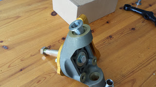
See fig 1 for what's in the box, and lets name the bits (from left to right, below the box):
1) Gold bit - a caliper mount.
2) Upright (note that this is the correct orientation for it).
3) Pointy bit (no idea what it's called)
4) Black bit (no idea what that's called wither)
5) Shim, and two washers.
On the box are also some bolts, more shims, a spacer and a nut.
Fig 2. Attach (1) to (2).

Step 1:

Fit the caliper mount to the upright using the three small bolts. When on the car, the mounting holes on the caliper should face to the rear of the car. Also, if you look carefully, on the large inner hole on the caliper mount there is a recess on one side. This recess should be on the outside as in fig 2.


Fig 3. Attach (3) to (2), not forgetting a washer.
Step 2:

Slide the pointy bit into the large hole in the middle, there is a large washer which fits nicely between the two. See fig 3.

Step 3:


Fig 4. The bolt holds (3) in place.
Turn it around and the nut fits nicely into the back of the pointy bit. Before putting the bolt in, pop the other large washer and the spacer in place. as in fig 4.

Step 4:

Screw the bolt onto the end of the pointy bit as in fig 5.

Step 5:

Fig 5. Add the bold to (3).
You can add a shim to the top and bottom mounting points on the upright now, but it's not worth it as they'll fall out and roll around your garage floor. This is where the drag link and ball joint will attach. See fig 6 for where they go.

And that's it, they can now be fitted to the car. Waitaminute I hear you say, what about the black bit and the other stuff?


Fig 6. Add the shims to (2).
Well, if you fit that now (not that I did of course, it's real hard to fit the upright to the ball joint, so I'd get the upright on the car first.

If you do test fit the black bit to the upright using the longer bolts, you'll notice that the bolts are too long. This is because the wheel arch mounts attach to the black bit too which spaces the bolts out.

One big caveat! This is how I did it and what made sense to me. I've no idea if this is the correct way or not, if I find out it's not, I'll edit this page and put a note at the top to say that it's changed. Hopefully no one will rely on this page and will have figured it out themselves or already know what they're doing and are only reading this so that you can have a laugh with your mates at how I've done it wrong and how the first pot hole I hit is going to eat my car :)

Left overs, they can't be important :)

More Front Suspension

In a proper workshop doing man things - not that kind of
man things! You have a dirty mind!!!
Previously on Front Suspension: I had fitted the bushes to the upper and lower wishbones but didn't have a vice big enough to fit the crash tubes inside the bushes... 

Luckily however there is a decent workshop at work, and Steve and Rob kindly let me loose in there. So I was able to use a proper vice and get them inserted. So easy with the right tools!

Back at the bat cave, I had to hammer the tubes into place, not as easy as you'd think. It's not a simple tap tap tap and in it goes, you properly have to twat them.

Offering up the wishbones to the car, and they don't quite fit, so I spent a fair bit of time filing the ends of the tubes down which took about an hour. I tell you what, my forearms are going to rule by the end of this project.

Wishbones fitted.
Fitting the drag links and ball joints was straight forward enough, so I figured I'd mount the wishbones. However, the bolts wouldn't fit the holes on the chassis due to it being painted, so more filing was required.

Finally the car has arms.

Springs and shocks in place.
The instructions that I have are for the Tr1ke which shares the front end with the Mevabusa, although being a 3 wheeler, it means that I have rear suspension too, which means more parts which look the same but are different. The springs are one example of this. They have different numbers on them, and I had no clue, so I broke my duck and posted on the official forums. Within minutes, a helpful chap had given me the answer (225 is front, 300 is rear), so off I went and fitted them to the shocks (I'm going to call them springs and shocks rather than coils and dampers). 

These were then fitted to the chassis and lower wishbone.

Uprights and caliper holders attached.
Next up are the uprights and associated gubbins, and this is where it got confusing as the pictures in the manual are nothing like what I have. I went through every box twice before settling on what must be them. A quick check of pics of the other builds and I'd guessed right. For anyone in the same predicament as me, I'll create a quick post on assembling these separately, but if I can figure it out I'm sure any 3 year old can.

What I haven't figured out yet is how the hubs fit on. I also have some bars to put on the inside which confused me for a little as the bolts were too long to attach them and I thought there should have been some more washers, but thinking about it, that's how the wheel arch struts attach which'll do that job.

I had wanted to fit the steering rack too, but I needed a 12mm drill and the biggest I had was 10mm, so I'll pick one up tomorrow. Instead I fitted the bushes to the rear wishbones (without the aid of the Bush Fitter 3000 [tm] you'll be glad to know).
It's starting to look a little more like a car now
rather than a climbing frame.


It's nice to see that the shocks are adjustable, I had adjustable shocks on an old mini once, they went from 1 to 24, with 24 being the stiffest. I put them on '5' under advise from my dad. The plan was to drive to my mates and then turn them up to 20 or something so that I could bounce the back end around, but even at 5 it was so stiff that the shocks went through the floor. Probably says more about the state of my mini really.


Tuesday, 27 August 2013

The Floor (Episode III)

With the bank holiday over, I could get my hands on somewhere that sells rivet nuts (lets call them rivnuts like all the cool kids), which are needed to fix the front floor.

I'd decided to switch from M3 to M4 nuts as I kept breaking my M3 tool as it was too small. So with this in mind I visited Rivet Holding Limited at lunch time to stock up.

Putting the floor in place as the sun set
I was glad I did, as upon arrival there was a nice Caterham style kit car outside with a Hayabusa logo on the back, so these were people I could relate to. The helpful guy who worked there sorted me out with a selection of nuts, bolts and washers all for a fraction of what I'd have paid online, so I well recommend them. He also had some suggestions for what to use later in the build so no doubt I'll be back (that wasn't an Arnold Schwarzenegger impression).

Tada! Note the bricks at the
front are not part of the kit.
After work, I had drilled out the smaller holes to take the larger M4 rivnuts and fitted them without a problem, the M4s really are much easier to work with than the flimbsy M3s.

And now the front floor is in place, it's time to flip the car, so I may need a hand, some unsuspecting person tomorrow is going to be lured into the task on the promise of a Creme Egg.


Monday, 26 August 2013

Front Suspension

For some reason, when envisaging building the car, it was always the suspension that seemed the fun part. No idea why, I know nothing about suspension systems, what they comprise of or how they work. Don't get me wrong, I know the buzz words, "wishbones", "shock absorbers", "coils", and I'm well aware of what a ball joint is as one broke on my 1275GT mini back in the day leaving me on 3 wheels in the middle of Kings Norton Green roundabout. Luckily this is next to a police station who's occupants dragged my car out of the way to free up the traffic, but I digress.


The suspension bits. Four wishbones, a bag of
bushes, a green box full of crush tubes, and in
the top right, a drag link. 
Following the instructions for a car similar to my car (they're still working on instructions for my actual car), it all looked quite easy.
Put some bushes in the wishbones, some tubes in the bushes, attach a ball joint and a drag link. So what's a drag link then? A quick Google Images search and I knew what to look for when rummaging through my boxes. Found them, right.

So the bushes in the wishbones. The instructions would have be squeezing them in by a vice, but alas, my vice is too small, so I borrowed a bigger one, which was also too small. One quick trip to the shops later and I have a multi-angle vice that's also yellow so that I don't lose it.

It appears that fitting the bushes into the wishbones is THE most frustrating task ever. Trying to get them to fit in evenly is near impossible, and I didn't want to damage them by forcing them. After 30 mins, I had one in out of sixteen and things were very close to be thrown around the garage. Time for a break.

After another twenty mins, I had another one in, not using the vice, but by squeezing with my hands, although this was more by luck as no others would go in that way. Time for a break.

As this is very frustrating and seemingly impossible, I figured other people would have a solution on their build logs. Apparently not, as no one else seemed to mention it at all. Hmm, what about if I scrap the vice method and make a tool? Ok, stop laughing, at this point you probably know enough about me to know that I've never made anything in my life, but I have a plan. I just needed a 12mm drill and I'd be fi... oh wait, biggest I have is 6.5mm, so lets bodge two holes together. 


Bush Fitter 3000 (c) 2013, all rights reserved, pat pending.
There we have it, a bush fitting tool, I'm going to call it a Bush Fitter 3000 [tm]. Ok, so it just looks like a nut and bolt with a square metal plate with two one hole drilled through it, but you wait and see.

Right, the Bush Fitter 3000 [tm] is an improvement, but it's still about as easy as doing a rubics cube while riding a unicycle and juggling (I did actually Google this to see if anyone has achieved it see http://www.youtube.com/watch?v=cRAwkwFMbSI although I still don't think it's easy!).


Taking a picture whilst holding
the wishbone and the
vice proved difficult.
While using the Bush Fitter 3000 [tm], I noticed how deformed the bush gets before snapping into the wishbone, so I went back to the vice method and just gave it some grief and it actually worked. This quickly turned into a technique (as my vice kept falling apart if I didn't do it in a particular way), and before you know it, all sixteen bushes were in place.

If anyone reads this and is hella frustrated about how to fit the bushes, give me a shout and I'll go through my technique. Having a vertical vice helped a lot! However I am willing to sell on the rights to the Bush Fitter 3000 [tm] if necessary.


All bushes in place.
There you go, bushes fitted. Now to put the crush tubes into the bushes. Again the vice is needed for this, but unfortunately even my new yellow vice is too small to fit it all in which is a bit of a problem. I tried without a vice, and it looks like this could be a challenge. Time to go and have a think about where to find a big vice.

The Floor (Episode II)

Compulsory artistic shot 
With the holes drilled the next job was to rivet. I had borrowed a rivet gun from someone which is the manual squeeze type. Each rivet takes 4 squeezes with the last one taking some girth.

I decided to do it in several sessions with 13-15 per session so that I'd be done in 10 sessions. This was to give my hand a break every now and then as it can start to hurt using this type of riveter. Reading someone else's build log, they were using an adapter for an electric drill which does the work for you, but these were £80, so I figured I'd do it the hard way.

I found that I had two types of rivets, both were exactly the same size, but one was slightly tougher than the other (known as "bastard rivets" or brivs for short). You never knew if you were going to get a briv or not, and believe me they really hurt to fit.

About 2/3s of the way in, I found that I could tell the brivs from the normal ones so quickly moved them about so that I never had to do two brivs in a row. 

The ten sessions were spread over two days and finally the main part of the floor was on. It looks quite neat at the moment, although I'm sure it will get scratched up pretty quickly once the car is on the road.

I'd decided to mount the front part of the floor separately to allow easy access to the pedals and whatever else goes in the front bit (probably loose change). This meant moving on from pop rivets to rivnuts. 

After some Googling to find out WTF rivnuts were and how they worked I ordered a bunch of M3 rivnuts and bolts to fit. I also opted for buying a rivnut gun rather than make my own which all the other YouTube people seemed to do.


Broken rivnut tool.
A couple of days later and I was ready to give it a go. 5 seconds later I was ready to down tools again. You see, when fitting rivnuts, you need a delicate hand, and not the same hand you used to fit pop rivets. If you do use the same force as you do with pop rivets then you quickly break the rivnut tool.

Back to eBay to order a new M3 mandrill for the tool.

Ok, take 2. Now with some more knowledge and a new tool I was able to fit 5 or 6 rivnuts before I threaded the new tool. Grrr. It turns out that M3 rivnuts have a really wieny thread, I should have gone for M4s instead.

The front part of the floor with the carbon wrap inside and
rubber strips around the edge.
Unfortunately it's now the bank holiday and nowhere is open to sell me M4 rivnuts. So the floor is going to have to wait for a bit which is frustrating as I desperately want to turn the car the right way up to crack on with the suspension. Once I have the tool it should be a fairly easy task...

I used some of the time to fit some rubber strips around the edge of the front floor to seal it a little better, this seemed to go ok which is odd, something went right first time! Hurrah!