Thursday 28 October 2021

Nearly there...

With a few more weeks in the workshop under the belt, progress has been rapido.

The car looks like it should work. The wings and wheel arches are in place, seats are in and most of the engine ancillaries are fitted.

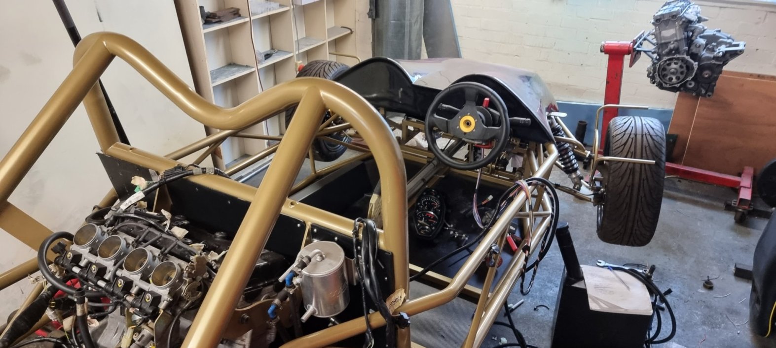
Apologies for no pics from the front, the car is close to a wall, so I couldn't get everything in shot, so you'll have to make do with ass shots.

So lets talk about the dashboard. For simplicity and to get it complete quicker, I'm using the dash from the bike. This may change in the future, but lets get a few laps on the clock first. Those with eagle eyes will notice that the dash is mounted upside down. This was due to some advice from an someone who builds race cars for a living... Basically, if it was mounted the correct way up then the rev counter would be way over to the left rather than in the drivers eye line. Mounting it this way, puts it in the peripheral vision especially when hitting the higher revs.

Here's a shot of the engine 'bay'. The throttle bodies and airbox are now in place amongst other stuff. I thought that the airbox would be uglier and stick up more, but as it is, I can live with it. There are alternatives, but they're not cheap, so it's another thing on the list to consider later. There's still more to be done back here, with the main bits being the starter motor and the gear shifter.

This is as close to a front view as it gets. The seats are in, and fit (phew). The drivers seat does need to go back a bit once the fuel tank is moved to the passenger side. This view does give a good view of the rear wing which is a monster! Lets hope it's better than the Countach rear wing which actually created lift.

I can't finish this post without giving a special shout out to Len of Wildmoor Motorsport. Len agreed to help me finish off this project along with Callum who works with Len. Sadly, Len passed away earlier this month which is a true loss to motorsport. Len was a top bloke and had a wealth of knowledge and experience and will be sadly missed. RIP Len.


Friday 27 August 2021

More oil

[I found this old unpublished post, I'm just going to hit 'publish' on it now, no idea why I didn't do it back in the day]
I ended a previous post on a cliff hanger, I'd just sheered a bolt when putting the sump back on. Not good.

I spent some time pondering what to do about this, can I bodge it? Do I need 14 bolts? If it's snapped far enough in, can I use a shorter bolt?

Do I drill it out? That sounds tough, especially lay on my back, drilling out a steel bolt from an aluminium engine lump. That could will go wrong. I consulted with my advisors; perhaps I could use the sump as a guide for drilling it out? Maybe use an extractor, then drill out a wider hole, tap it and fit a heli-coil.

I hadn't actually inspected the damage, so I attempted to remove the sump, I wasn't sure if it would come off as I didn't know where the bolt had snapped. It came off dead easy. Great. Even better news was that part of the bolt was sticking out, so I was able to get some purchase on it with some pliers. Turns out, I could get it out with my fingers, it was that easy. So basically, I made you read these last four paragraphs when I could just have said I unscrewed a bolt. Anyway, it was very relieving.

I took this to mean that the bolts were rubbish, so I got a new set of better ones and refitted the sump, and torqued them up without incident.

Sticking with the oil system, I purchased an oil cooler. As most things, this wasn't as easy as it sounded. The Hayabusa engine has some non-standard connections where the oil pipes connect, so I needed some way of getting off the shelf pipes to fit. Plus then when choosing an oil cooler there are four different standards for specifying the width of the inlets/outlets, of course the pipes that go on these use different terminology, so I can't just buy a size 8 cooler and size 8 pipes, that'd be way too easy.

After some hunting, I found that, the good guys at Extreme Engines do a conversion kit for the Hayabusa engine that converts the odd Suzuki format into one of these four standards (JIC/10). So it made sense to buy an oil cooler that was also JIC/10, then all I needed were some pipes to fit, oh and the pipe ends.

To help sort all this out, I contacted Speedflow who were very useful, and I send them my thanks! They can supply the cooler and the pipes, cut to length, and they'll fit the ends for me free of charge. 

At this point, as they were so helpful, I didn't bother shopping around as they deserved my business and ordered a 16 row, Mocal oil cooler. Again the size of the cooler was up for debate, and 16 rows might sound over the top for a 1.3l engine. However, the cooler does sit at the back of the car, so it's not going to get a lot of ram air, plus it's behind the hot engine. The only disadvantage that I could see for going for a larger one is that it may take longer for the engine to heat up, but that can be fixed if necessary.

So with the cooler delivered, I set about making the brackets, I know what you're thinking, I must be a dab hand at making brackets by now, but as always, everything is a challenge. With these brackets, the challenge was not having enough hands, and I ended up having to hold the cooler and the brackets in place and mark out the cuts using a Sharpie in my mouth.

The brackets holding the cooler in place.
I knocked up some prototype brackets in aluminium and then Steve at work created me a pair in stainless steel. I'd not worked with stainless before, and it's certainly more of a challenge than allooooominum!

So with the brackets made, I opted to paint them in the same colour as the chassis, MEV Exo cars had provided me with the RAL code of the paint colour, so I had some spray paint made up matching that and then went through the rigmarole of prime, paint and then lacquering.

Progress

Finally, some progress.
After another lengthy hiatus, work has started again, only possible as I now have help and the car is in a proper workshop.

Lots of decisions to be made, firstly I was never happy with the fuelling setup. Twin tanks complicates things and everything I read about them leads to problems. So the one behind the driver (me) can go. The tanks are 2.5 galleons each, so will be fine for a track day session. By losing the driver one, it also helps balance the weight if there is no passenger (even with a passenger, my COVID ballast will take some balancing!). 

Without that tank it also means that the driver seat can go backwards a little to give my lanky legs a little more room. However, there is also another use for that space which I'll get to later.

Next decision was around the gear changes. I wanted an electronic paddle shift, but that costs £££. From talking to the experts, they're also trouble, they need too much power and you risk losing spark and stalling which is something I'd rather avoid. An alternative is to go with hydraulics, but that costs £££££ and again is complex with either a compressor needed or having to top up a tank.

So the decision is to go with a stick shift, mechanical. It's not ideal, and will cost lap time, but not as much time as breaking down. Plus it will still be fun and I can always change when I save enough pennies.

The big progress has been the wiring, the loom is now extended and mostly in place. A lithium battery is on order, none of this old school acid or gel malarkey! This does beg the question of where to put the power commander, rectifier and all that gubbins. I wanted it under the nose cone on the passenger side, but that meant lengthening a load more cables, so it can go in the handy position which has just been made available behind the driver where the 2nd tank was going to be.

One more expenditure, a water pump. The pump on the 'busa lump isn't enough to circulate the now bigger system with the upgraded radiator that I fitted, so an additional pump is on it's way.

In the final picture here, you can also just make out the clutch slave is mounted on a custom bracket. Not sure how it's meant to go according to the kit, but as I never got a manual...