Monday 30 September 2013

Catchup...

It's been a while since I've provided an update for a few reasons, firstly my inane ability to procrastinate, but also because progress has been a little slow. Allow me to explain and bring you up to date on the various bits and pieces.

Steering Rack
Home made tool
The steering rack as you may remember needed disassembling so that a new rack and pinion could replace the standard Sierra bits. The new parts make it a quick rack, so basically less turns from lock to lock which will make the car a little more nimble on track.

The problem was that Ford decided to make just about everything that needed to be removed to require a custom tool. Obviously I didn't have a custom tool, so Steve at work used his wily brain and sorted things out. Fast forward a few days and I just needed to get the bearing off the old pinion and remove the spring system to allow to rack to come apart.

The bearing was on tight, tighter than a camel's bum in a sandstorm in fact. Luckily I had access to a big vice and an even bigger hammer. Bosh. Sorted.
Brand new but rusty,
going in the bin anyway

The spring system required some welding to make a tool to do the job. Of course, I'm not allowed anywhere near something like that, so Steve sorted it out while I hummed the A-Team soundtrack in the background. Once we had the tool it was easy work.

The rack was swapped out for the quick rack, but it was worth noting that even though the original rack was brand new, it still had signs of rust on it despite it never been used and covered in grease, it just shows what the shelf life does!

This is where the plastic nut needed to go. That's filings in
hole from work done to get it back in (don't worry, it was
cleaned out before put back together.
Putting it all back together wasn't simple either, the nut holding the spring system in was plastic and was easy to damage, mainly because Ford had 'knocked' in the metal around it so that it wouldn't slip. So a little bit of filing and lathe work and it was back in. It was prouder than before which was a worry to begin with but as the pinion it was pressing against was wider, that made sense.

The pinion cover that was tough to get off was tough to get back on too, Steve again sorted this as I don't think he fancied me throwing his tools through the window!

With that sorted I could do the rest at home. Now that probably doesn't read to hard, but as I did it at work, it was hard to get the time, and Steve's a busy man too, so it took a few weeks bit by bit, and my thanks do go out to Steve I'd probably have given up and kept the original rack!

Steering Column

The universal joint that connects
the column to the rack.
Ah, the column. I was dreading this as I read the instructions for it some time ago. It basically involved stripping the existing column, sawing a bit off, welding some bits together, then judging if it was right, then welding it again. I showed it Tim as he made this sort of 'hmm' noise, so we decided to put it to one side and come back to it later. Well it was now later.

Now, remember that the instructions that I'm following are for the Tr1ke, not my actual car, but this bit was all the same in theory as the front end was the same. That may be so, but Road Track Race (RTR) have made things easy since then by doing the cutting and welding already. I didn't realise this though for some time, so much so that I'd told the good folks there that I was missing a part but when Harry from RTR dropped in one evening he put me right. Doh.

So with that sorted, it was kind of easy. Ok lining up the rack so that the wheels were straight as well as the steering wheel is a little more difficult, but I got it close enough for now.

Fittings and Fixtures

A collection of nuts'n'bolts. Lets hope there
are none left over at the end.
In my last post I moaned a little bit about having run out of nuts'n'bolts, as well as a bunch of parts. Well the very next day harry from RTR turned up with some more bits. It was mainly pipes and hoses as well as the Power Commander (which looks a bit complicated, but I haven't had a proper look yet). He was able to answer a bunch of questions that I had as well as looking at what I was missing. He then put together a list of bolts and they arrived in the post a few days later.

This meant that I could swap out all the odd sized bolts that I'd been using to get things in place. One wishbone for instance was held in place by a pencil and a cable tie.

So there we have it, the steering now works, plus lots of little bits have been able to be finished properly (like the brake pedal, wishbones, etc).

Next up, stripping the bike for parts....

Tuesday 17 September 2013

Hayabusa

Small progress...
Not too much progress on the kit itself. I started assembling the rear corners, with the correct way of putting it together being the last one I tried. I've now officially run out of nuts and bolts that RTR provided with my kit, so I'm waiting on them before I can continue with that part.

The steering rack hasn't got much further either, I've been too busy at work to pop to the workshop to get the bearing off the rack pinion, it's stuck on pretty firm! I definitely want to get that sorted this week so that I can get the quick rack in and on the car. However, I can't finish up the steering column as I'm waiting for some parts for that from RTR too.

There is something I can crack on with now though, I've just got back from collecting the donor bike. It was quite a journey, after spotting it on Preloved a week ago I contacted the owner who was in Edinburgh (I'm in Birmingham) and after a couple of chats decided to fly up to see it. I'd booked a one way ticket, so it was really all-eggs-in-one-basket as if I didn't like it when I got there I'd have to hitch hike home or something.

So this morning I started the journey by driving to work, leaving my car there, got some odd lucks because I was in my biking textiles and boots, and walked to the train station. Two trains later I was at Birmingham International, so a quick mono-rail journey to the terminal and I got on the midday plane to Scotland.

At the airport, Gary, the guy who was selling the bike met me. I was initially confused as his description of himself was 'big guy wearing glasses and t-shirt', although when he eventually found me (not many people get off a plane in biking gear), he wasn't wearing glasses at all (they were in his pocket), so I think I can be excused from that :)
I parked next to a bin, that isn't a top box.

Turns out that Gary is a sound bloke, not only did he pick me up from the airport, we had a good natter about biking before going out on a test ride. He was on his TL1000 and i was on the 'Busa. There was a little issue with the front brake sticking as it had been stood for a while, but who needs brakes on a 200mph bike huh? It's not like I was planning on a 5 hour ride home on it or anything...doh!

Back at his place and we got the business done, I insured the bike but couldn't tax it (it was SORNed), as the DVLA couldn't see the insurance as it had just been done. So I decided to ride home tax free.

I hit the road at about 3:30pm, along some great roads which eased me into the bike a bit. It was nice and dry for the first 45mins but then the road got damp and after an hour I stopped for a comfort break. Just as I got inside, the rain broke and tipped it down, but stopped as soon as I went outside again, good timing!

Onward to the motorway, which is where the bike really showed its legs. The Hayabusa's are legendary for being a quick bike and up til then I was a little disappointed with the performance, compared to my KTM it wasn't that quick at lower speeds. On the motorway though, it was a different story, it went from 70mph to ..urm... 71mph (I'll let you use your imagination!), very quickly. The speedo reads up to 220mph and although I didn't get it anywhere near that, I could feel the potential. Best stop for fuel.

Another stop and another well timed shower and I was back on the road, full of KFC (mandatory on a long UK road trip) with just 100 miles to go. My luck of dodging the rain ran out at about Stafford, but still it was only light rain, but at night it really made it hard to see where I was going and for some reason everyone stopped indicating and driving like an idiot, so I eased off a bit and tried to get some circulation back in my body.

Finally I was off the motorway, and back in Birmingham, just a short trip down the A38 and I was home. However, I soon had that horrid thing in my mirrors, the blue lights of a Police X5 flagging me down. 

For the record, the officer was very pleasant
The policeman said "Mmm mmm mmmmm", so I took out my ear plugs and asked him to repeat that, and it turns out that his computer had told him that I didn't have insurance. I explained that I'd just riden back from Scotland five, I mean six hours ago (good catch), and showed him an email from my insurance company providing that I had insurance. He was fine with that and off I went.

So there we have it, a car journey, 2 trains, a monorail, a plane, another car, and a 5 hour bike journey later and I was back where I started but with a Hayabusa in my garage.

The 'busa in it's new home
My KTM is still off the road since the nice lady with the Land Rover pulled out on me, so I may hang fire for a couple of weeks before starting to take it apart. 


Monday 9 September 2013

I hate steering racks

Progress has been slow recently for a couple of reasons. Firstly, I'm waiting for a few bits of the kit, although this isn't a major problem as there are lots of things to do, it does mean that lots of things aren't quite finished. Secondly the instructions are still work in progress, so I'm using the Tr1ke manual which is doing me ok for now, but things are starting to differ between the builds, I appreciate that this is a busy period for RTR though, so I imagine it'll turn up as we head into the autumn. Oh and the last reason why progress is slow, well that's mostly because I'm rubbish :)

I didn't think leaving the keys in would be much of a
security issue at this point.
It seems ages since my last update, and not a lot has changed. On the corners I have the cycle wing struts in place as well as the black bits which I now know are called steering arms (who'd have known).

I moved onto the steering rack and column. The column was pinned in place with the u-bolt, so although it's nice to see a steering wheel in place, it does feel like a little bit like I'm building a Ford Ka. 

The rack is a little more complicated. Physically fitting it was fairly easy, although I had to borrow a large enough drill bit (12mm) and then realised why I didn't have one, which was because my 'leccy drill only has a 10mm chuck. I was however due to pop around to Tim's house to water his garden (if you're reading this in the winter, think back to those lovely summer days) as he's away, but forgot to take my backpack with me and I was only my motorbike. So it was a fun journey home trying to hold a drill and ride a bike, but I made it alive, so those two holes took two days to drill, such is my slow progress.

The rack does need some internal work doing to. It's a standard Sierra rack, which needs converting to a quick rack which is supplied. However, our friends at Ford must hate me as they've the way the rack is assembled makes it very difficult to undo.

The instructions glossed over a little about how hard it was to undo the steering rack ends. So much so that I had to check on the forum that I was trying to undo the right section, I was, and everyone (including people on a Ford forum) agreed that it takes a bit of grunt! Apparently I don't have grunt, so I needed a new plan.
Steering rack ends, both difficult to Google for as well
as undo.

I decided that I needed to use the big vice at work again for this, and Steve the workshop manager who I will now refer to as God2 (don't want to piss off the actual God should be exist) lent a hand. God2 clamped the rack rather than the housing which made it much easier, he also used some serious grips.

The grips that did the job in the end.
Next the aluminium cover was removed, this time however in the instructions it had the warning: This is very difficult to undo. Turns out it wasn't so bad, with God2's advice a drill bit was used rather than a centre punch as it's pretty tough and just the right size.

So that's about it for now, it seems like I've written a page just to say "drilled two holes and undid a couple of screws" but it's more about how 2 little pictures in the manual can take up most of a week for someone like me.

We had to call it a day as God2 had to leave and I wasn't expecting so much progress so had left some bits at home, so tomorrow will be spent finishing the internals of the steering rack.

Sunday 1 September 2013

Assembling the uprights

As in my previous post More Front Suspension, I'd found that the pictures and instructions that I was following for the Tr1ke varied to the Mevabusa. 


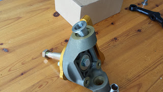
Fig 1. The contents.
See fig 1 for what's in the box, and lets name the bits (from left to right, below the box):
1) Gold bit - a caliper mount.
2) Upright (note that this is the correct orientation for it).
3) Pointy bit (no idea what it's called)
4) Black bit (no idea what that's called wither)
5) Shim, and two washers.
On the box are also some bolts, more shims, a spacer and a nut.
Fig 2. Attach (1) to (2).

Step 1:

Fit the caliper mount to the upright using the three small bolts. When on the car, the mounting holes on the caliper should face to the rear of the car. Also, if you look carefully, on the large inner hole on the caliper mount there is a recess on one side. This recess should be on the outside as in fig 2.


Fig 3. Attach (3) to (2), not forgetting a washer.
Step 2:

Slide the pointy bit into the large hole in the middle, there is a large washer which fits nicely between the two. See fig 3.

Step 3:


Fig 4. The bolt holds (3) in place.
Turn it around and the nut fits nicely into the back of the pointy bit. Before putting the bolt in, pop the other large washer and the spacer in place. as in fig 4.

Step 4:

Screw the bolt onto the end of the pointy bit as in fig 5.

Step 5:

Fig 5. Add the bold to (3).
You can add a shim to the top and bottom mounting points on the upright now, but it's not worth it as they'll fall out and roll around your garage floor. This is where the drag link and ball joint will attach. See fig 6 for where they go.

And that's it, they can now be fitted to the car. Waitaminute I hear you say, what about the black bit and the other stuff?


Fig 6. Add the shims to (2).
Well, if you fit that now (not that I did of course, it's real hard to fit the upright to the ball joint, so I'd get the upright on the car first.

If you do test fit the black bit to the upright using the longer bolts, you'll notice that the bolts are too long. This is because the wheel arch mounts attach to the black bit too which spaces the bolts out.

One big caveat! This is how I did it and what made sense to me. I've no idea if this is the correct way or not, if I find out it's not, I'll edit this page and put a note at the top to say that it's changed. Hopefully no one will rely on this page and will have figured it out themselves or already know what they're doing and are only reading this so that you can have a laugh with your mates at how I've done it wrong and how the first pot hole I hit is going to eat my car :)

Left overs, they can't be important :)

More Front Suspension

In a proper workshop doing man things - not that kind of
man things! You have a dirty mind!!!
Previously on Front Suspension: I had fitted the bushes to the upper and lower wishbones but didn't have a vice big enough to fit the crash tubes inside the bushes... 

Luckily however there is a decent workshop at work, and Steve and Rob kindly let me loose in there. So I was able to use a proper vice and get them inserted. So easy with the right tools!

Back at the bat cave, I had to hammer the tubes into place, not as easy as you'd think. It's not a simple tap tap tap and in it goes, you properly have to twat them.

Offering up the wishbones to the car, and they don't quite fit, so I spent a fair bit of time filing the ends of the tubes down which took about an hour. I tell you what, my forearms are going to rule by the end of this project.

Wishbones fitted.
Fitting the drag links and ball joints was straight forward enough, so I figured I'd mount the wishbones. However, the bolts wouldn't fit the holes on the chassis due to it being painted, so more filing was required.

Finally the car has arms.

Springs and shocks in place.
The instructions that I have are for the Tr1ke which shares the front end with the Mevabusa, although being a 3 wheeler, it means that I have rear suspension too, which means more parts which look the same but are different. The springs are one example of this. They have different numbers on them, and I had no clue, so I broke my duck and posted on the official forums. Within minutes, a helpful chap had given me the answer (225 is front, 300 is rear), so off I went and fitted them to the shocks (I'm going to call them springs and shocks rather than coils and dampers). 

These were then fitted to the chassis and lower wishbone.

Uprights and caliper holders attached.
Next up are the uprights and associated gubbins, and this is where it got confusing as the pictures in the manual are nothing like what I have. I went through every box twice before settling on what must be them. A quick check of pics of the other builds and I'd guessed right. For anyone in the same predicament as me, I'll create a quick post on assembling these separately, but if I can figure it out I'm sure any 3 year old can.

What I haven't figured out yet is how the hubs fit on. I also have some bars to put on the inside which confused me for a little as the bolts were too long to attach them and I thought there should have been some more washers, but thinking about it, that's how the wheel arch struts attach which'll do that job.

I had wanted to fit the steering rack too, but I needed a 12mm drill and the biggest I had was 10mm, so I'll pick one up tomorrow. Instead I fitted the bushes to the rear wishbones (without the aid of the Bush Fitter 3000 [tm] you'll be glad to know).
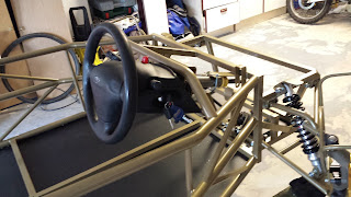
It's starting to look a little more like a car now
rather than a climbing frame.


It's nice to see that the shocks are adjustable, I had adjustable shocks on an old mini once, they went from 1 to 24, with 24 being the stiffest. I put them on '5' under advise from my dad. The plan was to drive to my mates and then turn them up to 20 or something so that I could bounce the back end around, but even at 5 it was so stiff that the shocks went through the floor. Probably says more about the state of my mini really.