[I found this old unpublished post, I'm just going to hit 'publish' on it now, no idea why I didn't do it back in the day]
I ended a previous post on a cliff hanger, I'd just sheered a bolt when putting the sump back on. Not good.I spent some time pondering what to do about this, can I bodge it? Do I need 14 bolts? If it's snapped far enough in, can I use a shorter bolt?
Do I drill it out? That sounds tough, especially lay on my back, drilling out a steel bolt from an aluminium engine lump. That
I hadn't actually inspected the damage, so I attempted to remove the sump, I wasn't sure if it would come off as I didn't know where the bolt had snapped. It came off dead easy. Great. Even better news was that part of the bolt was sticking out, so I was able to get some purchase on it with some pliers. Turns out, I could get it out with my fingers, it was that easy. So basically, I made you read these last four paragraphs when I could just have said I unscrewed a bolt. Anyway, it was very relieving.
I took this to mean that the bolts were rubbish, so I got a new set of better ones and refitted the sump, and torqued them up without incident.
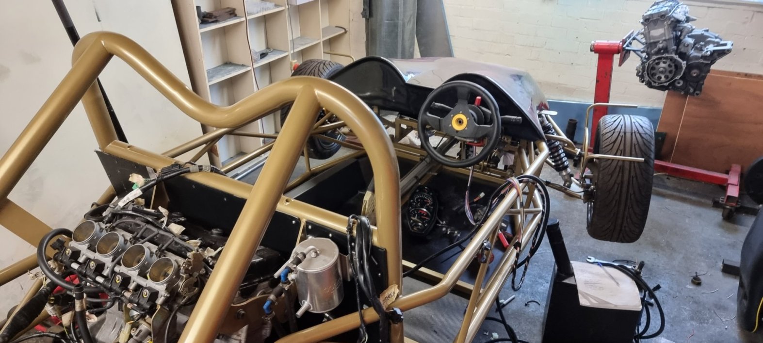
Sticking with the oil system, I purchased an oil cooler. As most things, this wasn't as easy as it sounded. The Hayabusa engine has some non-standard connections where the oil pipes connect, so I needed some way of getting off the shelf pipes to fit. Plus then when choosing an oil cooler there are four different standards for specifying the width of the inlets/outlets, of course the pipes that go on these use different terminology, so I can't just buy a size 8 cooler and size 8 pipes, that'd be way too easy.
After some hunting, I found that, the good guys at Extreme Engines do a conversion kit for the Hayabusa engine that converts the odd Suzuki format into one of these four standards (JIC/10). So it made sense to buy an oil cooler that was also JIC/10, then all I needed were some pipes to fit, oh and the pipe ends.
To help sort all this out, I contacted Speedflow who were very useful, and I send them my thanks! They can supply the cooler and the pipes, cut to length, and they'll fit the ends for me free of charge.
At this point, as they were so helpful, I didn't bother shopping around as they deserved my business and ordered a 16 row, Mocal oil cooler. Again the size of the cooler was up for debate, and 16 rows might sound over the top for a 1.3l engine. However, the cooler does sit at the back of the car, so it's not going to get a lot of ram air, plus it's behind the hot engine. The only disadvantage that I could see for going for a larger one is that it may take longer for the engine to heat up, but that can be fixed if necessary.
So with the cooler delivered, I set about making the brackets, I know what you're thinking, I must be a dab hand at making brackets by now, but as always, everything is a challenge. With these brackets, the challenge was not having enough hands, and I ended up having to hold the cooler and the brackets in place and mark out the cuts using a Sharpie in my mouth.
 |
| The brackets holding the cooler in place. |
So with the brackets made, I opted to paint them in the same colour as the chassis,